
When you’re looking at a plumbing blueprint, you’re essentially translating a set of symbols, lines, and scales into a real-world, functional system. The trick is to start with the legend to get a handle on the symbols, then follow the water supply and drain lines, making sure to cross-reference the different views like floor plans and isometrics.
Why Reading Plumbing Blueprints Is a Critical Skill
Before you even think about tracing a single pipe, you have to appreciate why this is such a non-negotiable skill in the trades. These drawings aren’t just lines on paper; they are the official language of any construction project. Get one symbol wrong, and you can set off a chain reaction of expensive, time-consuming errors.
Just imagine meticulously installing a waste line, only to find out you’ve put it exactly where the HVAC plan shows a massive duct run. A clash like that isn’t a small hiccup. It means demolition, costly rework, blown deadlines, and a serious hit to your professional reputation. Reading the blueprint correctly from the very beginning is what stops these thousand-dollar mistakes before they happen.
The Language of Collaboration and Compliance
Your skill in reading these documents directly affects how well you can work with every other trade on the job site. Plumbing systems don’t exist in a vacuum; they have to weave through and around everything else in the building.
When you can confidently read a plan, you can spot potential conflicts with electrical conduits or HVAC systems long before you start cutting and gluing. This foresight is a massive factor in keeping a project running smoothly and on schedule.
A blueprint is a promise of what can be built. Your ability to read it is your commitment to fulfilling that promise accurately and safely. It builds trust with general contractors and makes you an invaluable part of the team.
This literacy is also your guarantee that every fixture and pipe you install meets the strict local building codes and the architect’s specific engineering requirements. It’s the foundational skill for turning a complex diagram into a safe, reliable plumbing system that will function perfectly for decades.
Building Your Foundational Knowledge
Blueprint literacy isn’t something you learn overnight; it’s a skill that sharpens with every project you tackle. It’s what connects the hands-on work you do every day with the project’s big-picture vision, transforming you from just an installer into a true problem-solver.
If you’re completely new to construction documents, a quick guide for beginners on how to read blueprints offers a fantastic starting point. Getting this foundational knowledge under your belt allows you to anticipate challenges, order the right materials the first time, and execute your work with confidence and precision.
Where to Begin: The Title Block and Legend
Every single set of plumbing blueprints has a clear starting point. I can’t tell you how many times I’ve seen rookies make the mistake of just jumping right in and trying to trace a pipe run. Before you do anything else, your eyes need to go directly to the title block and the legend.
Think of it this way: these two elements are your instruction manual and your dictionary for the entire job. Skipping them is like trying to build a complex piece of furniture without looking at the directions.

You’ll almost always find the title block tucked away in the lower right-hand corner. This little box contains the project’s vital statistics. It’s where you find the official project name, the architect or engineering firm that drew it up, the drawing scale, and—most importantly—the revision dates.
Trust me, overlooking that revision date is a classic blunder. You could end up working from an outdated plan, a mistake that guarantees a costly and frustrating callback.
What to Look for in the Title Block
Before you even think about the pipes, scan the title block for these key details. It only takes a minute and can save you hours of headaches.
- Project Name and Location: First things first, make sure you’ve got the right set of plans for the right job site. It happens.
- Sheet Title: This tells you exactly what you’re looking at. Is it the “First Floor Plumbing Plan” or a “DWV Riser Diagram”?
- Drawing Scale: This is absolutely critical for taking accurate measurements. A common scale is 1/4″ = 1′-0″, but it can vary wildly depending on the detail level.
- Revision History: This shows if the plan has been updated. If you see multiple revisions, triple-check you’re working from the latest one.
The technology for creating blueprints has changed, but the core skills haven’t. Mastering how to read symbols, dimensions, and system layouts is as important as ever. Getting comfortable with the title block and legend is the first real step.
Unlocking the Symbols with the Legend
Once you have your bearings from the title block, the legend is your next stop. This is your Rosetta Stone for the entire plumbing blueprint. It’s what translates all those abstract symbols and different line types into real-world pipes, fixtures, and valves.
Don’t just glance at it. Take a moment to actually study it. This is where you’ll see exactly how the designer differentiates between a cold water line (often a solid line) and a hot water line (often shown as a dashed line). It will show you the specific symbol for a floor drain versus a cleanout, or a gate valve versus a ball valve.
The practice of blueprint reading actually has a long history, dating back to the cyanotype process invented by Sir John Herschel in 1842 that created those iconic white-on-blue prints. While most of our plans are digital now, the fundamental need to decode these symbols correctly has never changed. You can actually learn more about the history and evolution of blueprints if you’re interested.
Take the time to commit the main symbols to memory. It builds the confidence you need to read the rest of the plan quickly and, more importantly, correctly.
Decoding Common Plumbing Symbols and Lines
Once you’ve got a handle on the legend, you’re ready to start speaking the blueprint’s language. This is the fun part—where you move from the project’s big-picture logistics to the nitty-gritty details of the plumbing system itself. Think of the symbols and lines as the vocabulary and grammar that bring every pipe, fixture, and valve to life on the page.
Learning to read these at a glance is what really separates a rookie from a seasoned pro. It’s more than just knowing a circle with “WC” inside means “water closet.” It’s about instantly seeing how that toilet connects to the larger Drain, Waste, and Vent (DWV) system, which is usually drawn with heavier, more prominent lines.
This is the skill that helps you visualize the entire system in three dimensions. You’ll start to see past the flat paper and imagine the network of pipes weaving through walls and floors. That’s a crucial step for doing accurate material takeoffs and planning an installation that won’t clash with HVAC or electrical runs.
Distinguishing Between Line Types
Before you even start picking out fixtures, you need to be able to tell the pipes apart. Most plans use different line styles to make this clear. With a bit of practice, a quick look should tell you exactly what’s flowing through each pipe.
Here are the most common ones you’ll run into:
- Cold Water Supply: Look for a solid, unbroken line (
———). This is your main artery, bringing water into the building and branching off to every fixture needing a cold supply. - Hot Water Supply: This is almost always a dashed or broken line (
- - - - -). You’ll trace these from the water heater to sinks, showers, dishwashers, and washing machines. - Drain, Waste, and Vent (DWV): These are the workhorses of the system and are typically drawn with a thicker, heavier solid line. Since DWV lines rely on gravity, getting their layout right is absolutely critical.
- Gas Lines: These are often drawn with a distinct pattern, like a line with a letter in the middle (
— G — G —), to make sure no one mistakes them for a water line.
Being able to see these different lines clearly helps you mentally separate the pressurized supply system from the gravity-fed drain system. This is one of the most fundamental skills in reading any plumbing plan.
Identifying Key Fixture and Fitting Symbols
With the line types sorted, the symbols for fixtures and fittings start to fall into place. Your legend is the ultimate authority here, but many symbols are pretty standard across the industry. Getting familiar with them will dramatically speed up your ability to read and understand a plan.
I’ve put together a quick reference table with some of the symbols you’ll see on almost every job.
Common Plumbing Blueprint Symbols and Their Meanings
| Symbol Category | Specific Symbol | What It Represents | Key Detail to Note |
|---|---|---|---|
| Fixtures | Rectangle with two small circles | Kitchen or Lavatory Sink | The number of circles indicates hot and cold taps. |
| Fixtures | Circle with “WC” | Water Closet (Toilet) | Pay attention to its position relative to the main drain stack. |
| Fixtures | Circle with “FD” | Floor Drain | Crucial for utility rooms, basements, and commercial kitchens. |
| Fittings | Triangle symbol (filled or open) | Valve (Gate, Globe, etc.) | The specific design of the triangle tells you the valve type. |
| Fittings | Circle with “CO” | Cleanout | Provides access for snaking the drain line; location is key. |
| Piping | Dashed line rising vertically | Vent Pipe | Indicates a pipe going up through the roof or connecting to a vent stack. |
This is just a starting point, of course. For instance, a kitchen sink might be a simple rectangle, while a utility sink could have a slightly different shape or label. The small details are what matter.
I’ve seen this happen on site: a young plumber mistakes a Cleanout (CO) for a Floor Drain (FD). It’s an easy mistake to make if you’re moving too fast. But one is for maintenance access, and the other is for draining the floor. Mixing them up can cause major headaches and code violations down the road.
It’s the same with valves. A gate valve and a ball valve have different symbols because they do different jobs. One is great for on/off control, while the other is better for throttling flow. The blueprint specifies which one to use for a reason. Vent pipes are another make-or-break component. Recognizing their symbols is non-negotiable for a properly functioning DWV system. If you want a refresher on why they’re so important, you can learn more about how a plumbing vent works and see why a healthy system depends on them.
When you combine your knowledge of lines and symbols, the blueprint stops being a confusing mess of marks. It becomes a clear, logical map of an interconnected system. You can trace the journey of water from the city main, through the heater, out a faucet, and finally down the drain and out of the building.
Getting a Feel for Scale and Different Views
Plumbing isn’t a flat, two-dimensional world, and the blueprints that map it out aren’t either. One of the biggest hurdles when you’re starting out is learning to build a 3D picture in your head from a bunch of 2D drawings. It’s a skill you build over time, and it all starts with understanding the different views.
Think of it like this: you can’t understand the shape of a house from just one photo. You need the front view, a side view, and maybe an overhead shot to really get it. Blueprints do the exact same thing for a plumbing system, giving you a complete picture of how pipes will twist and turn through walls, floors, and ceilings.

The Three Views You Need to Master
To really understand how a system flows, from a single fixture all the way back to the main stack, you have to get comfortable flipping between three core views. Each one tells a different part of the story.
- Plan View: This is your classic “bird’s-eye” view, looking straight down. It’s your go-to for figuring out the horizontal layout—where the toilet sits in relation to the vanity, or how far the kitchen sink is from a wall.
- Elevation View: Imagine you could slice a wall open and look at it from the side. That’s an elevation. This view is critical for seeing vertical pipe runs, like how high a shower valve needs to be or where a vent pipe punches through the roof.
- Isometric View: We often just call this a “riser diagram” in the field. It’s a 3D-style drawing that shows both the vertical and horizontal runs at the same time. Honestly, this is the money shot for understanding a complex Drain-Waste-Vent (DWV) system and how it all ties together.
The real trick isn’t just knowing what each view is. It’s about mentally layering them. You’ll use the plan view to find the toilet’s location, switch to the elevation to check the water line height, and then trace its drain line through the whole system on the isometric view.
Cracking the Code of Architectural Scale
Once you can see the layout in your mind’s eye, you need to know what it all means in the real world. That’s where the architectural scale comes in, and you’ll always find it noted in the title block of the print. A very common one you’ll see is 1/4″ = 1′-0″. All that means is that every quarter-inch on the drawing equals one foot on the job site.
Don’t get spooked by the fractions. This is where your best friend comes in: the architect’s scale ruler. It’s that triangular ruler that looks way more complicated than it is.
Here’s how you actually use it on the job:
- First, find the scale on the blueprint (let’s stick with 1/4″ = 1′-0″).
- Grab your scale ruler and spin it until you find the side marked “1/4”.
- Line up the “0” on the ruler with one end of the pipe or wall you’re measuring.
- Look at where the other end of the line falls on the ruler. That’s your measurement in feet. Simple as that.
This isn’t just an academic exercise; it’s absolutely essential for accurate takeoffs and rough-ins. For example, the scale tells you a drain line needs to be 10 feet long, but you still need to know exactly where to stub it out. Our guide on standard https://professional-plumbers-denver.com/blogs/bathroom-rough-in-dimensions/ is a perfect resource for translating those scaled drawings into the real-world measurements you need. Nail this, and you’ll avoid the massive headache of realizing a pipe won’t fit where the drawing says it should.
Tracing a Plumbing System from Start to Finish
Alright, let’s put it all together. You can stare at symbols and different views all day, but the real test is tracing a whole system from start to finish. This is where the lines on the paper stop being just lines and start becoming a living, breathing plumbing system in your head.
Think of a typical residential job. First thing you do is find the main water supply line coming into the property. The site plan will usually show you exactly where that is. This is your ground zero. From that point, you’ll follow the main cold water line as it travels through the foundation and starts to split off.
One of the first major branches you’ll see will run straight to the water heater (look for that WH symbol). As soon as it hits the heater, a new line comes out—the hot water supply. You can usually tell it apart because it’s drawn as a dashed or otherwise distinct line. Now you’ve got two paths to follow: the solid cold line and the dashed hot line, running side-by-side to feed sinks, showers, and appliances.
Following the Flow of Water
What you’re really doing here is mapping the journey the water will take. Tracing these supply lines helps you visualize every connection point, every turn, and every spot you’ll need to install a shut-off valve. It’s all about building a mental map before you touch a single pipe.
- Start at the Source: Always, always begin where the water main comes in.
- Find the Split: Pinpoint where the line tees off to feed the water heater.
- Trace to Each Fixture: Methodically follow both hot and cold lines to every single fixture on the plan. No skipping.
This simple exercise is a game-changer for planning an efficient install. You’ll know exactly which of your essential plumbing tools you’ll need to have ready for each phase of the rough-in.
Tracing the Drain Waste and Vent System
Once you’ve got the supply side down, it’s time to switch gears to the Drain, Waste, and Vent (DWV) system. For this, the isometric view or riser diagram is your best friend. I always start at the highest fixture in the building—say, a sink in a second-floor bathroom.
You’ll see the P-trap from the sink tying into a drain line. Notice how that line slopes down to meet a much larger vertical pipe—that’s your stack. Follow that stack downward, paying close attention as other fixtures, like toilets and showers, connect into it. You’ll also see smaller pipes branching off and heading up. Those are your vent lines, and they’re just as important as the drains; they let the whole system breathe.
This image gives you a good look at the logic behind pipe sizes and slopes—two details that make or break a DWV system.
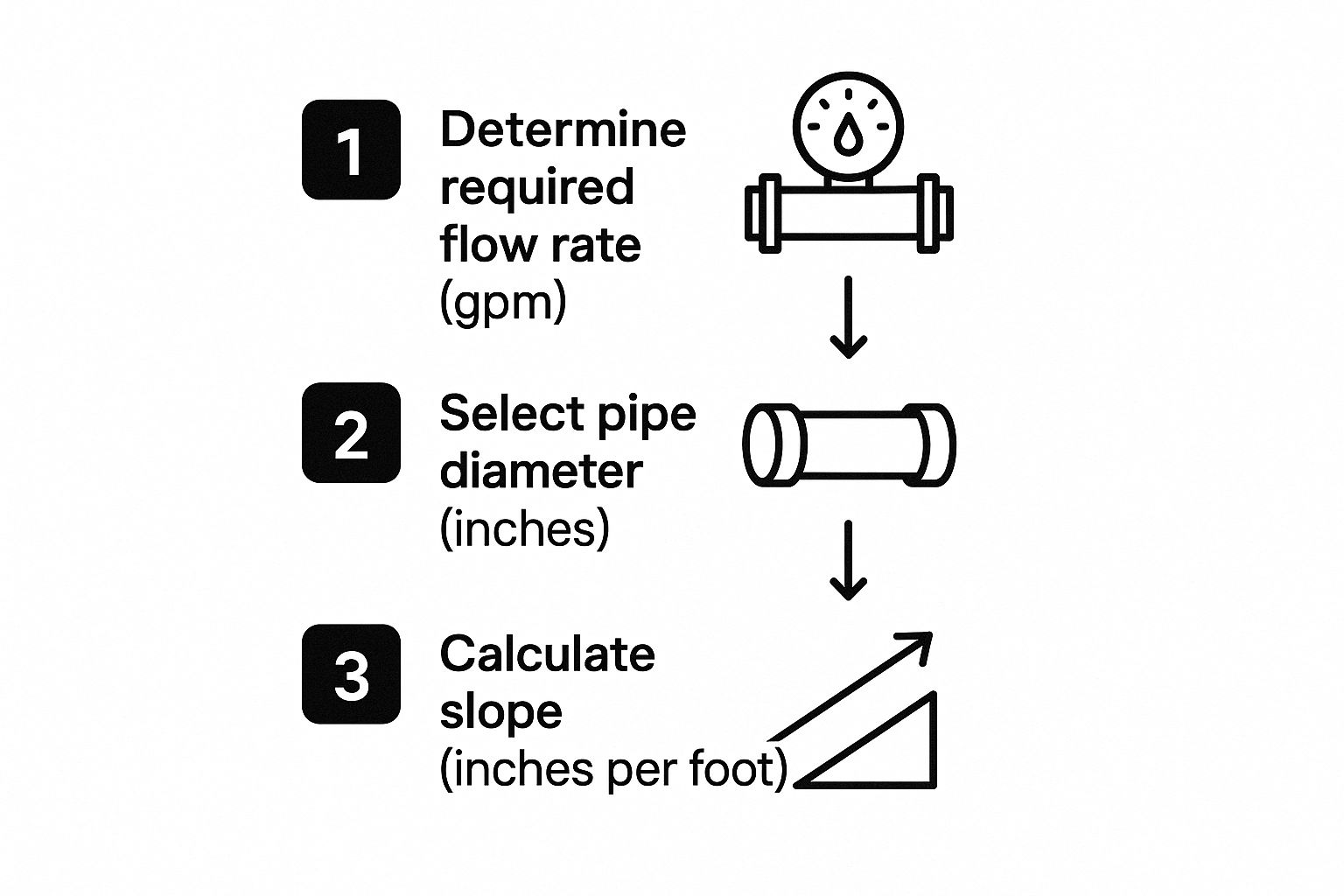
It’s a great visual reminder that the flow rate tells you the pipe size, and the pipe size dictates the proper slope you need for gravity to do its job.
Tracing the DWV system is non-negotiable. You have to confirm that every single fixture has a proper vent and that every drain line has the correct slope called out in the notes. This is where the most expensive mistakes happen.
Finally, follow that main stack all the way to the lowest level of the building. You’ll see it turn from vertical to horizontal and head out of the foundation to connect to the sewer main. Taking the time to do this full trace is crucial. In fact, studies show that plumbers who are trained to thoroughly review legends and trace systems from end to end can finish jobs up to 30% faster and with far fewer callbacks.
Common Questions About Reading Plumbing Blueprints
https://www.youtube.com/embed/fr8CXkczYKw
Even after you’ve spent years tracing lines and decoding symbols, you’re going to run into situations on the job site that make you pause. Honestly, navigating these tricky spots is what separates the pros from the apprentices.
Let’s walk through some of the most common questions we hear, from greenhorns and seasoned plumbers alike, when it comes to figuring out a set of plumbing plans. These aren’t just textbook scenarios; they’re the real-world hiccups that can either stop a job in its tracks or let your expertise shine.
What’s the Difference Between a Plan View and an Isometric Drawing?
This is a big one, and it trips up a lot of people just starting out. Think of it this way: the plumbing blueprint is the whole package of 2D drawings. It includes the “plan view,” which is your bird’s-eye view looking straight down. It’s like a map showing you the horizontal layout and exactly where every fixture lands in a room.
An isometric drawing, on the other hand, is a specific diagram within that set of plans. It’s drawn to look 3D. While the plan view tells you where everything goes, the isometric shows you how it all connects. It’s absolutely essential for visualizing the vertical runs of a complex Drain-Waste-Vent (DWV) system as it snakes between floors.
What Should I Do If a Symbol Isn’t in the Legend?
It happens more often than you’d think, especially on older prints or plans that were rushed out the door. The absolute last thing you should do is guess.
First, scan the general notes section of the drawing. Sometimes an unusual symbol is defined there instead of in the main legend. If that’s a dead end, use the context around it.
- Is the symbol sitting on a hot or cold water line?
- Is it part of the drain system?
- Where is it in relation to the known fixtures?
If you’ve checked the notes and the context and are still scratching your head, the only professional move is to submit a Request for Information (RFI) to the architect or engineer. A wrong guess can easily cost thousands in rework. When in doubt, always ask.
Are Digital Blueprints Better Than Paper Copies?
Digital plans on a tablet or laptop have some huge advantages. You can pinch-to-zoom on a tiny detail without squinting, use built-in tools to measure a pipe run instantly, and even toggle layers to hide the electrical and HVAC clutter. It makes focusing on just the plumbing a whole lot easier.
But remember, the tech is a tool, not a replacement for skill. You still need to know how to read the plan in the first place. One pro tip: if you’re working with older scanned plans, it’s worth learning how to make PDF searchable. Being able to quickly search for a specific note or label in a huge document can save you an incredible amount of time on site.
At Professional Plumbers Denver, our work is built on a deep understanding of the trade, from interpreting the most complex blueprints to executing a perfect installation. Whether it’s a simple fixture swap or a full commercial rough-in, you can trust our experienced team. Contact us today for all your Denver plumbing needs at https://professional-plumbers-denver.com.

Recent Comments